Ernie's Thunderstorm/N8
Upgrade
This is a short chronicle of
my XLH1200 upgrade:
-
Installing appropriately sized
Wiseco
Buell Thunderstorm K1700 series pistons
-
Installing Buell Thunderstorm
cylinder heads
-
Installing Andrews
N8 cams
-
Honing the (and it turns out
bore) cylinders
Updated 28 August 1999.
START WITH DISASSEMBLY:
Put bike in fifth gear.
The remove carb, exhaust, tank, etc. per engine strip-down instructions
in the FM. I removed the exhaust in one piece as suggested by Rickko.
In order to remove the rear the rockerbox, you'll need a shorten allen
wrench or a rocker box wrench (Like the one I have). To remove the
intake manifold, you'll need a shortened allen wrench (like the one I have)
or a ball allen wrench (I've heard this works). Reason for these
two special tools: Those socket head screws are in incredibly tight
space locations. To remove exhaust in one piece, unbolt the mufflers
from the frame (front) and bracket (rear). Unscrew the socket head
screws attaching the exhaust pipes to each of the cylinder heads.
The whole exhaust comes off in one piece.
Why fifth gear? Well,
you want to make the lower rocker box removal to be easy - you just roll
the rear tire (I just rolled the bike) to make sure that both the intake
and exhaust ports are closed on the cylinder you are working on.
This releases pressure on the rocker arm that you are working on.
I drained the oil when I
did the cams.
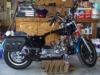 |
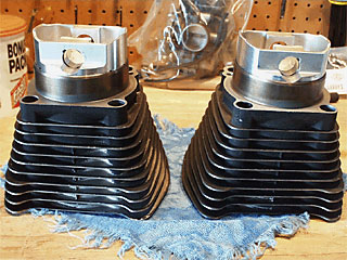
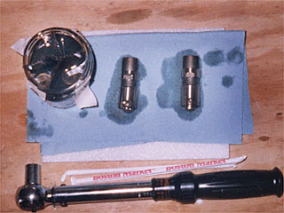
The Sportster is stripped
of engine parts down to the case. The cylinders were shipped to DWR
Race Support in Arizona for honing and selection of matching Wiseco
K1700 series pistons. The push rods and tubes are in the foreground. Below
the screwdrivers in the background are the CV carb and ignition module
(and Arai F/F helmet).
I used a small flat bladed
screw driver to pop the retaining ring off of the pinion pin (wristpin).
Now I have two very expensive cigar ashtrays (pistons). The cigars can
be stuck in the wristpin holes to hold the stogies. |
 |
The pistons are out and
the cylinder studs are protected with 0.5" ID plastic tubing. The base
contact with the case is almost cleaned. The tappets have not been removed
at this point. Old socks keeps crud from falling into the case.
To remove the rocker boxes,
put in fifth gear and see that intake and exhaust ports are closed on the
cylinder you are working on. Makes removal easier. |
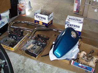 |
Parts be parts. I have
parts in labeled ziplock bags. For example, the front motor mount and all
its hardware is in one "Front Motor Mount" bag. BTW I will mill out the
slots on the front motor mount to accept the hardware for the Thunderstorm
heads.
On the left are the rear
and front standard XLH1200 heads, rockerbox covers, and all associated
hardware. The exhaust came off as one piece - ala Rickko. The Corona boxes
are empty of the precious fluid but full of baggied parts. |
Remove the tappets after
removing the tappet pin plate and pins. I used a Craftsman magnetic
pick-up to lift up and remove the tappets (Thanks Moshe). I completely
submerged the tappets in clean oil making sure that the tappets went back
to the same holes (Front Exhaust - FE, Front Intake - FI, RE, RI).
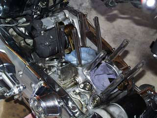
THE CAM SWAP:
Drain oil and remove oil
filter. Remove the cam cover. First remove the timing covers
and gasket, sensor plate screws, sensor plate (disconnect the ignition
sensor connector), rotor bolt, and rotor. I really ought to change
the cam shaft oil seal also. Then I removed a hose that connects
to the cam cover. This allowed me to remove the cam cover without
it dangling from anything.
 |
Remove the cam cover.
I unscrewed the 11 screws in order of the torque sequence. Before
you start removing the socket head screws, make a cardboard cut-out of
the cam cover. You see, the cam cover screws are not all the same
so when you remove a screw, put it in it's appropriate place on the cardboard
cam cover cut-out.
I drained the oil prior
to cam cover removal. Couple of things: (a) some oil
will drip out (b) make sure bike is in fifth gear for cam gear alignment.
At this point, you may choose to see that the cam timing markers are aligned
according to the FM. I chose an alternate approach. |
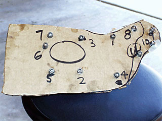 |
A magnificent piece of
art, eh? It'll eliminate a lot of heartache later. With this
crude method, you'll know where all the appropriate screws go on the cam
cover. This is great advice given by Maurice.
This cardboard cut-out is
labeled with the torque sequence. |
 |
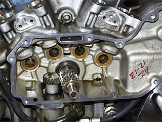
Checking the new Andrews
N8 cams for fit as recommended on the Andrews Products homepage.
By placing the cams in the cam cover and rotating each cam gear, you can
check for any binding or looseness.
It's a nice simple check
and gives you a feel for how precise the gears are. |
 |
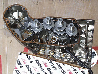
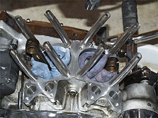
Ok, the four cam gears
are removed from the case. From left to right, the cam bushings hold
cam #1, #2, #3, and #4. The gear sticking out of the crank case is
the pinion gear. It has a timing mark which is an indented mark on
one of it's teeth. That marker is used to align with the timing mark
of cam #2.
If you've pre-aligned the
gears, just remove cam #4 and replace with new; Remove cam #2.
Remove and replace cam #3. Remove and replace cam #1. Replace
cam #2 making sure the timing markers are aligned. I did not pre-align
so did not follow this procedure. |
|
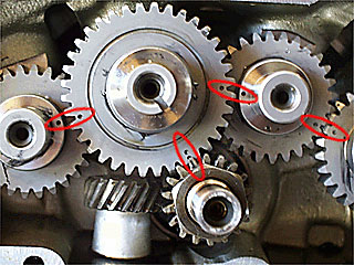
There is one timing marker
on cams #1 and #4, two timing markers on cam #3, and three markers on cam
#2. I installed as follows: Remove all old cam gears.
Cam #2 must be removed before #1 and #3. Use lots of assembly lube on the
shafts (I also put it on gears). Install new cam #2. Rolling
the bike (rear wheel) back and forth, align one of the cam #2 timing markers
to the pinion gear timing marker. Remove cam #2 and install cam #1
then #2 so that the cam #1 and #2 timing markers line up (a cam #2 timing
marker must be aligned with pinion gear). Remove cam #2.
Re-install cam #3, then #2 (but not all the way in). Adjust (rotate) cam
#3 to match timing marker on cam #2 (a cam #2 timing marker must be aligned
with pinion gear). Push in cam #2 all the way and then install and
align cam #4 timing marker to a cam #3 marker. Viola! Now put
lots of assembly lube on the cam gear shafts that will go into the cam
cover bushings.
Wipe the cam gasket surfaces
clean. Use wooden skewers to mount up the gasket. Remove all
but a few skewers on top and place cam cover on, using the skewers for
alignment. |
Use half of the 11 screws
to secure the cover back on and then remove the skewers. Put remaining
screws on and tighten to 80 - 110 in-lbs following the torque sequence.
 |
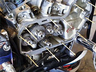
The base is cleaned and
ready for cylinder installation after installing the pistons.
I used a non-scratch nylon
pot scrubber (with water), old credit card to scrape, and VERY careful
low angle application of a single-edged razor with VERY little force to
lift stubborn gasket material off of the case.
WOW! Nice and shiney! |
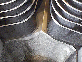
PISTON INSTALLATION IN
CYLINDERS
The cylinders were bored
for 0.020 over-bore by DWR due to out-of-roundness, excessive taper, and
small scratches on the wall of one of the cylinders. So they matched
the 0.020 Over Bore with the K1702 pistons. They also set the rings
for me.
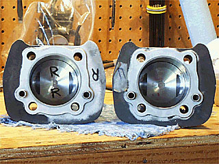
Be sure the pistons are
appropriate for the cylinder and appropriately aligned - The exhaust port
direction is marked on K1702 pistons. |
The preferred way as written
in the FM is to install the pistons on the connecting rod, position base
gasket, and using a piston ring compressor on lubricated rings, slide the
cylinder down onto the piston, guided by the cylinder studs.
Make sure you use a well lubricated ring compressor that "comes apart"
- like the one you use for VW's. PEP
BOYS has one for under $11.
I broke my ring compressor...
You can bust out laughing now... So I did it the Tatro/Rickko way.
Turn cylinders upside down. Assembly lube the first 2-3 inches from
the top of the upside-down cylinders and lubricate remaining part of the
cylinder walls with engine oil.
The place the rings in the
proper orientation as shown in the FM - basically the ring gaps are pointed
at the cylinder stud holes. Install one retaining ring for the wristpin
in each cylinder. I installed on what is to be the tappet side.
Turn pistons upside-down, place it on the upside-down cylinder, resting
on the first (compression) ring. Squeeze the ring and place the ring
gap in the cylinder. Gently work the remainder of the ring into the
cylinder. Repeat for all rings. I did lightly tap on the pistons
with the palm of my hand to press the pistons in the cylinders - it's a
snug fit. DON'T PUSH THE PISTONS ALL THE WAY IN. Leave the
wristpin hole on the pistons clear. |
Now we're ready to install
each piston and cylinder combo. Place the base gasket in its place.
I used the HD base gasket since (a) it has print-o-seal so no messy Hylomar
(b) there is a small lip where the crank case halves meet so I figured
the fiber HD gasket might seal better than the Aluminum Bartel's gasket
- very subjective. Slide the cylinder-piston combo onto the cylinder
studs, align and install the piston on the connecting rod with an assembly
lubed wristpin. Install a retaining ring. I pushed the end
of the ring opposite the gap into the piston retaining ring groove then
used needle nose pliers to push the two ends into the gap. BTW:
I installed the first wristpin retaining ring on the tappet side so that
when installing the piston-cylinder combo, I wouldn't drop the ring into,
say, the tappet holes!
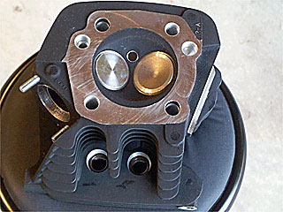
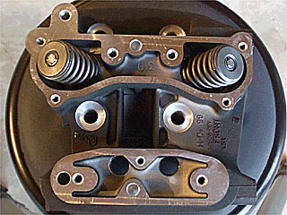
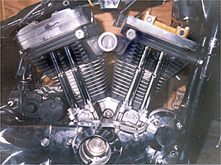
The front Thunderstorm head.
Note the combustion chamber. It's not a hemi like the stock XLH1200
heads. Instead, it's a bathtub shape. Also check out the pretty
valves. |
The valve springs are heftier
too since the the heads are design for 10:1 compression.
Basically, it's a better
quality 1200 head.
|
The rear base gasket is
placed and the rear piston/head combo is installed. There are two ways
that I installed the pushrods/down tubes. At any rate, shown are my rear
(exhaust and intake - left and right respectively) tappets. |
On left is the jar full
of oil with quadrant dividers that held the tappets soaking in fresh oil
- you can see the two remaining tappets submerged in oil. Torque
wrench (the clickity-click kind) at bottom. Also straws for my margarita
glass - since my hands were greasy.
 |
At this point, gently drop
the tappets into their holes. It only orients one way, as the tappet
pins will not go in if it's oriented in the wrong way. The rollers
should allow for rolling motion front to back of the bike.
So the two ways of installing
the pushrods and tubes: Method one (Rickko's) is to install the pushrod
tubes (with pushrod seal) before installing the heads. I did this
for the rear cylinder. Method two is per FM: Install the cylinder
head first, then install the pushrod tube by tilting the tube and pushing
the top end into the tube hole in the head, then sliding the bottom onto
the tappet hole. Make sure that you slide one the pushrod seal and
other hardware over the pushrod tube prior to installing the tube.
There is one minor modification
necessary when installing the Thunderstorm heads. They use 7/16"
threads on the front upper motor mount instead of 3/8" like the stock heads.
I widened the slots with a milling machine in the front upper motor mount.
Instead of using a stud in the left front like the stock bikes, I just
installed the motor mount on the front head loosely with two grade 8 7/16"
bolts BEFORE installing the head on the cylinder, then tightened them after
the heads were torqued down. I decided against using a stud since
I felt a bit lazy in the mind that day.
As far as gaskets, I used
standard H-D gaskets for the most part. The exception was the use
of the Bartel's copper head gasket (top-end gasket) kit. I did not
use the Bartel's Aluminum base gaskets. The H-D base gaskets with
the print-o-seal was used since there is a slight lip where the two halves
of the case meets and I fully agreed with Maurice's "feeling" that the
H-D base gasket might seal better than the Bartel's Aluminum gasket.
NAPA copper gasket spray was used for the Copper head gaskets, and Gaskecinch
everywhere else - except the base gaskets since they already had the print-o-seal.
The main thing is: USE NEW GASKETS!
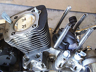
The front rocker arms are
shown. I also installed the intake manifold before I closed up the
front rocker box. The pushrods are installed while the lower rocker
box is loosely attached to the head. |
A wider view of the install
prior to closing up the upper rocker box cover. It's starting to
look like a bike again.
|
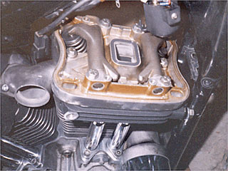
The base gaskets look really
great!
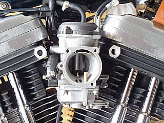
The rocker boxes are closed up and the carburetor is installed. |
I have other pics of the
carburetor including the wheel where the throttle cables attach if there
is interest in seeing these pics
 |
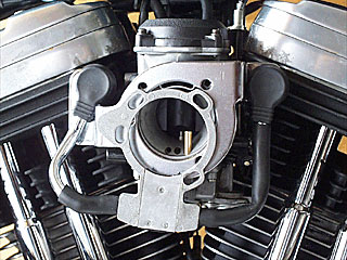
The KuryAkyn breather -
not attached yet. The Hypercharger goes over this get-up. No
drippy oil air-box syndrome using this set-up. |
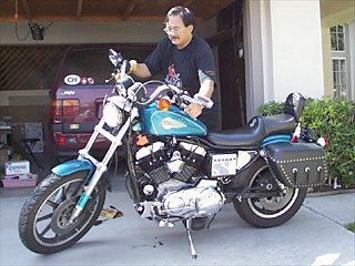
Finally! The moment
of truth yields a low growling THUMP, THUMP, THUMP. Some minor idle
speed adjustment, and the bike was ready for a test ride.
 |
Before starting the engine,
push the starter and allow her to turn few cranks WITHOUT spark plugs.
This will allow some oil pressure to build. It will also allow you
to feel air coming out of the spark plug holes giving reassurance that
the pistons are pumping. And that WHOOSHING AIR - what a feeling!
When the bike is first started up, it'll be making all kinds of louder
than usual metallic sounds as the parts get lubed. Not to worry,
it'll mostly go away after a few minutes. Then adjust idle speed
and mixture if necessary. I adjusted the idle speed, but did not
have to change the idle mixture (yet).
Final Notes
Well, it turns out the 5/16"
screw holding the front exhaust pushrod tube was not holding right since
the heli-coil insert that was in there came out. So there was an
oil leak from that area. I had an inde use a TimeSert bushing to
fix that problem.
The bike pinged. I
also had a SE Programmable Ignition Module - basically a Dyna 2000 Programmable
Module. Played with the advance curves and timing. Still had
some ping. So I installed a '96 later SE Ignition module with 6800
rpm rev limit and QSE curve. What a difference! I'll report
after a longer test period, but it looks like a good fix.
Overall performance observation:
There is a little tappet noise, but it's expected. The sound is very
different. It's got a low GROWL (not a rumble) with a very noticeable
THUMP-THUMP-THUMP instead of the potato-potato-potato that we are all accustomed
to hearing. Nice smooth throttle response with torque through the
rpm range. It really likes to be in the 2500+ rpm range. There
is definitely more HP and torque available. Translation: The
bike be FAST !
Photos were taken by my
neighbor Andrea who takes digital images of items for a variety of applications
for her business. She wanted to digitally clean up the background but I
told her that if things looked too clean, bikers would get suspicious.
BTW: There are a couple of poor quality photos that I took while
Andrea was on vacation. She did a great job digitally enhancing them,
but I think you can still tell which photos are mine.
HAPPY HAPPY JOY JOY!!
If you'd like to email Ernie:
 Do it here.
 Go
to Ernie's Piglet.
Go
to Ernie's Piglet.