Next: Questions:
Up: Procedure:
Previous: Part B: Ammeters, Voltmeters,
Contents
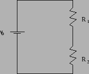
Set up the circuit shown below, and measure the voltages
across
 and
and  .
.
Read off the value of the resistors, the value of the
voltage of the power supply, and predict or
calculate
the expected voltages across the resistors. What current flows through
each resistor? Decide this from the measurements of the
voltages without using an ammeter. Are the currents the same
or different? Which should they be?
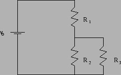
After this, add a third resistor in parallel with , as shown
below.
Record the value of the third resistor in your lab book, and
predict what will happen to the current through the other
two resistors. Will the currents through them increase, decrease, or
stay the same? Try to give an answer without using an
equation.
Once you have thought about it and recorded an explanation, measure
and record all the voltages and determine the currents through
each resistor and whether or not you had the right idea.
Next: Questions:
Up: Procedure:
Previous: Part B: Ammeters, Voltmeters,
Contents
greg severn
2000-10-24